Welding Joint Types and Positions: Butt, Tee, Lap, Corner, Edge and 1G-6G
There are five basic weld joint types: butt, corner, T, lap, and edge. They describe how two pieces of metal meet. Welding position describes how the joint sits relative to gravity: flat, horizontal, vertical, or overhead. Codes like 1G or 2F combine a position number with a weld type letter, G for groove and F for fillet.
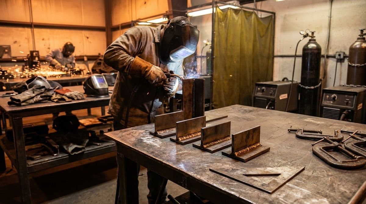
From the guide: Types of Welding Processes Explained: MIG, TIG, Stick, Flux-Core and More
A weld joint is the way two pieces of metal fit together, and a welding position is how that joint sits in space while you weld it. Both decide which process you pick, how you set the machine, and how hard the job will be. This page covers the five joint types and the four basic positions, then explains codes like 1G and 2F. It is a companion to our overview of the main types of welding processes, which shows which process fits which joint.
Joint type and position are separate ideas. A T-joint can be welded flat, horizontal, vertical, or overhead. A butt joint can too. Keep them apart in your head and the rest gets easy.
What Are the 5 Types of Welding Joints?
The five basic weld joint types are butt, corner, T-, lap, and edge. AWS A2.4, the standard behind welding symbols, recognizes these five, and almost every joint you meet in shop work is one of them or a mix.
| Joint | How the pieces meet | Typical weld |
|---|---|---|
| Butt | Same plane, edges meeting or with a root opening | Groove |
| Corner | Two pieces at 90 degrees, forming an L | Fillet or groove |
| T-joint | Edge of one piece meets the flat face of another at about 90 degrees | Fillet |
| Lap | Two surfaces overlap | Fillet |
| Edge | Edges parallel or nearly parallel | Groove edge preparations |
The definitions and “typical weld” column come from Miller Electric’s joint guide. The sections below take each one in turn.
What Is a Butt Joint?
A butt joint joins two pieces that lie in the same plane, with their edges meeting or with a gap called a root opening between them. Miller Electric lists a groove weld as the typical weld.
Butt joints are the standard way to join plate, sheet, and pipe end to end. Because the weld has to join the full thickness, two decisions come first: whether the edges need preparation (a bevel) or a square groove is enough, and whether the joint needs a root opening. Miller says proper fit-up reduces welding problems.
A tip for beginners: practice butt joints on thin steel with a MIG machine first. Our MIG welding guide for beginners covers setup and technique.
What Is a T-Joint?
A T-joint forms when the edge of one piece meets the flat surface of another at about 90 degrees. Miller Electric lists a fillet weld as typical.
T-joints are common in frames, brackets, and structural work. Miller’s tips are practical:
- Weld from both sides to improve strength.
- Place the weld on the side that will experience stress.
- Use a 45-degree work angle for proper penetration on both pieces.
Miller also says T-joints can be welded fairly easily in the flat, horizontal, vertical, or overhead position, which is why they are a good joint for practicing different positions.
What Is a Lap Joint?
A lap joint has two pieces whose surfaces overlap, with the weld deposited where they intersect. Miller Electric lists a fillet weld as typical.
Lap joints suit sheet metal and repair work because they need little edge preparation and forgive imperfect fit-up. Miller suggests:
- Weld both sides of the overlap for added rigidity.
- Use more overlap on thicker material.
- Make the pieces as flush as possible before welding.
What Is a Corner Joint?
A corner joint joins two pieces at 90 degrees to form an L shape. Miller Electric says either a fillet weld or a groove weld can be used.
On thin material, corner joints can burn through. Miller advises increasing travel speed on thinner materials with open corner joints. Fit-up matters too, because the angle has to be right to limit distortion. Boxes, frames, and enclosures are typical corner joint jobs.
What Is an Edge Joint?
An edge joint is formed when the edges of the workpieces are parallel or nearly parallel. Miller Electric advises using it only where there is no significant impact or heavy stress.
For more penetration or rigidity, Miller suggests a groove edge preparation, such as square, V, J, or U, and welding all four sides for added reinforcement. Edge joints show up in thin sheet and in flanged parts. Because Miller limits the joint to light-duty use, confirm with the design before using one on anything loaded.
What Are the 4 Basic Welding Positions?
The four basic welding positions are flat, horizontal, vertical, and overhead. Miller Electric pairs each with an F for fillet welds or a G for groove welds, so 1G is a flat groove weld and 2F is a horizontal fillet weld.
The numbers run 1 to 4: 1 is flat, 2 is horizontal, 3 is vertical, and 4 is overhead. Here is what the four mean in practice.
Flat position (1G and 1F)
Flat is the easiest position, because you are not fighting gravity. Miller calls it generally easier to weld in. Any process works. Keep the wire or electrode centered, since an off-center angle can cause incomplete fusion. With stick welding, use a drag technique to manage slag. Our stick welding guide covers rod handling.
Horizontal position (2G and 2F)
In the horizontal position, the weld runs sideways. Miller says a 2G weld is slightly more difficult than a 2F weld. For groove welds, angle slightly toward the top edge to manage the puddle’s sag. For fillet welds, hold about 45 degrees. Avoid running too hot, which makes the puddle too fluid.
Vertical position (3G and 3F)
On a vertical weld, the puddle naturally sags, so flat and horizontal settings usually will not work. Miller says vertical-up is more common, especially on thick material. Reduce wire feed speed and voltage, and use a 90-degree travel angle for 3G and 45 degrees for 3F. Techniques like zigzags or triangles help you hold the weld toes and move quickly across the middle of the puddle. Practice on scrap first.
Overhead position (4G and 4F)
Overhead welding is often necessary for fixed equipment or immovable metal. Miller recommends finding a comfortable position with good range of motion, using vertical-style techniques with a slight weave at 4G, and running cooler to keep the puddle from dropping.
Overhead work is also where burns happen. Falling spatter and slag land on you, so wear a fully leather jacket and cover your head under the helmet. Review our welding safety and PPE guide before you try it.
What Do 1G, 2G, 3G, 4G, 5G and 6G Mean?
Position codes describe how a joint is oriented relative to gravity, not what kind of joint it is. Steelmax explains that the number identifies the position and the letter identifies the weld type: F for fillet and G for groove. A welder tested on a 3G groove has welded a vertical groove joint, not necessarily a horizontal one.
Plate groove positions
| Code | Setup |
|---|---|
| 1G | Plate lies flat; welder works from above |
| 2G | Plate stands vertical; the seam runs horizontally across it |
| 3G | Plate stands vertical; the seam runs up or down it |
| 4G | Plate lies flat; welder works from underneath |
Plate fillet positions
| Code | Setup |
|---|---|
| 1F | Joint tilted so the weld pool sits in a symmetric pocket and gravity helps |
| 2F | One plate flat, one upright; welder works from the side |
| 3F | Same joint as 2F, but the seam runs vertically |
| 4F | Joint hangs above the welder, who works from underneath |
Pipe groove positions
Pipe codes work differently, according to Steelmax. The number still signals difficulty, but 5G and 6G exist because a fixed pipe cannot be rotated into the flat position.
| Code | Setup |
|---|---|
| 1G | Pipe lies horizontal and rotates, so the joint stays flat |
| 2G | Pipe stands vertical and fixed; welder moves around it |
| 5G | Pipe lies horizontal and fixed; the weld passes through flat, vertical, and overhead sections |
| 6G | Pipe fixed at a 45-degree incline; combines flat, vertical, and overhead in one joint |
| 6GR | Same as 6G with a restriction ring near the joint; a tougher test |
Steelmax says passing a 6G test is generally accepted as qualifying a welder for all positions. Treat that as a general statement. What a given test qualifies you for depends on the code and the procedure you test under, so check with the test facility. Our welding certifications guide explains how certification tests are set up and administered.
Which Welding Processes Work in Which Positions?
Position limits come from the process, the transfer mode, and the filler metal, not from the joint. Miller Electric says TIG, short-circuit MIG, and pulsed MIG work in all positions, spray-transfer MIG is limited to flat and horizontal, and stick and flux-cored welding depend on the filler metal.
That is why electrode and wire data sheets list approved positions. For stick electrodes, Miller notes that the third digit of the electrode number shows the acceptable positions: 1 means all positions, 2 means flat or horizontal only, and 3 is flat, horizontal, vertical down, and overhead. Check this against your actual rod before you weld out of position. Our welding rods and electrodes guide explains how to read those numbers.
For TIG, which works in every position but demands steady hands, see the TIG welding guide.
How Do You Choose the Right Joint and Position?
You rarely choose freely. The designer picks the joint and the drawing or procedure sets the position, but you can still influence both when you fabricate your own parts.
Use these rules of thumb:
- Pick the joint from the load. Put weld metal where the stress is, and weld both sides when the design allows it.
- Weld flat whenever you can. Positioners, clamps, and turning the work all bring a joint back to flat, where welds are easier and cleaner.
- Match the process to the position. Do not plan an overhead pass with a process or transfer mode limited to flat work.
- Prepare the joint. Check fit-up, root opening, and bevel before striking an arc.
- Follow the procedure. On code work, the welding procedure specification governs position, joint design, and filler.
On drawings, the joint and the weld are shown with symbols. Our guide to reading welding symbols shows how a fillet or groove weld is called out.
Reading Joints on a Drawing
Drawings call out each joint with a weld symbol. Our welding symbols explained guide shows how to read one, and the weld symbols chart lets you check each symbol as you go.
Common Mistakes With Joints and Positions
Most beginners trip on the same things:
- Poor fit-up. Gaps and misalignment cause defects and distortion on any joint.
- Wrong settings out of position. Flat settings sag on vertical and overhead welds, so reduce heat as Miller advises.
- Confusing joint and position. A butt joint can be flat or overhead, and the code changes the settings, not the joint.
- Skipping PPE for overhead work. Spatter lands on you from above.
- Assuming a position qualifies you everywhere. Qualification depends on the test code and the procedure.
Start with flat T-joints and butt joints, move to horizontal, and only then try vertical and overhead with a supervisor or instructor. Practice on scrap, and match the process to the position.
Questions we get
What are the 5 types of welding joints?
The five basic weld joint types are the butt joint, corner joint, T-joint, lap joint, and edge joint. AWS A2.4 recognizes these five. A butt joint has two pieces in the same plane, a corner joint forms an L, a T-joint meets one piece's edge to another's face, a lap joint overlaps two surfaces, and an edge joint joins parallel edges.
What is the strongest type of weld joint?
No joint type is strongest in every case, because strength depends on the load direction, joint design, weld size, penetration, and welder skill. Butt joints with full-penetration groove welds are common where strength matters. Miller Electric also suggests welding T-joints from both sides and placing the weld on the side that will see stress. The design drawing or engineer decides, not a rule of thumb.
What do 1G, 2G, 3G, and 4G mean in welding?
They are position codes for groove welds. The number gives the position: 1 is flat, 2 is horizontal, 3 is vertical, and 4 is overhead. The letter G means groove. So 1G is a flat groove weld and 4G is an overhead groove weld. Fillet welds use the letter F in the same way, as in 1F through 4F.
What is the hardest welding position?
Overhead is generally considered the hardest because the welder works against gravity and the molten puddle wants to drop. Miller Electric advises running cooler to keep the puddle from falling and wearing a fully leather jacket and a bandana under the helmet, especially for stick welding. On pipe, a 6G test is a demanding position because it combines flat, vertical, and overhead welding in one joint.
What does a 6G weld test qualify you for?
A 6G test uses pipe fixed at a 45-degree incline, so one joint passes through flat, vertical, and overhead positions. Steelmax notes that passing it is generally accepted as qualifying a welder for all positions. The exact limits come from the code and procedure you test under, such as AWS D1.1 or ASME Section IX, so confirm the details with the test facility before you test.
What is the difference between a fillet weld and a groove weld?
A fillet weld is a roughly triangular weld placed in the corner where two pieces meet at an angle, as on a T-joint or lap joint. A groove weld fills a prepared opening between two pieces, as on a butt joint. Miller Electric lists groove welds for butt joints and fillet welds for lap and T-joints, with corner joints using either.
Can you use any welding process in any position?
No. Miller Electric says TIG, short-circuit MIG, and pulsed MIG work in all positions, but spray-transfer MIG is limited to flat and horizontal. Stick and flux-cored welding depend on the filler metal. Always check the electrode or wire data sheet for approved positions and follow the welding procedure specification for your job.
Where we got this
- A Guide to the 5 Basic Types of Weld Joints and Tips for Improving Results — Miller Electric (millerwelds.com)
- What Are the 4 Basic Welding Positions and When Should You Use Them? — Miller Electric (millerwelds.com)
- Stick Welding for Equipment Repair: Electrodes, Equipment and Technique — Miller Electric (millerwelds.com)
- Welding Positions Chart — Steelmax (steelmax.com)
- NCDOT Field Welding Procedures Manual, Appendix C (reproduces AWS A2.4 clauses on joint types) (connect.ncdot.gov)
- AWS A2.4:2012 — Standard Symbols for Welding, Brazing, and Nondestructive Examination (pubs.aws.org)
Keep reading
- Types of Welding Processes Explained: MIG, TIG, Stick, Flux-Core and More
Learn the 4 main types of welding—MIG, TIG, Stick, and Flux-Core—how each works, compatible metals, and how to pick the right process.
- Flux-Core Welding (FCAW) Guide: Self-Shielded vs Gas-Shielded
Learn flux-core welding (FCAW): self-shielded FCAW-S vs gas-shielded FCAW-G, DCEN vs DCEP polarity, knurled drive rolls, drag technique, and fume safety.
- MIG vs TIG Welding: Differences, Costs and When to Use Each
Compare MIG vs TIG welding on speed, weld appearance, skill level, gas requirements, and equipment cost to pick the right process for your project.
- MIG Welding for Beginners: Setup, Technique and Common Mistakes
Learn MIG welding (GMAW) step by step: wire sizes, C-25 gas flow rates, DCEP polarity, gun angle, travel speed, and how to fix common weld defects.
- Stick Welding (SMAW) Guide: Rods, Amperage and Technique
Learn stick welding (SMAW): how E6010, E6011, E6013, and E7018 rods work, polarity and amperage ranges, arc striking, drag technique, and safety.
- TIG Welding Guide: How GTAW Works and How to Start
Learn TIG welding (GTAW) step by step: DCEN vs AC polarity, argon flow, tungsten prep, filler technique, and safety rules.