Welding Amperage Chart: Settings by Process and Thickness
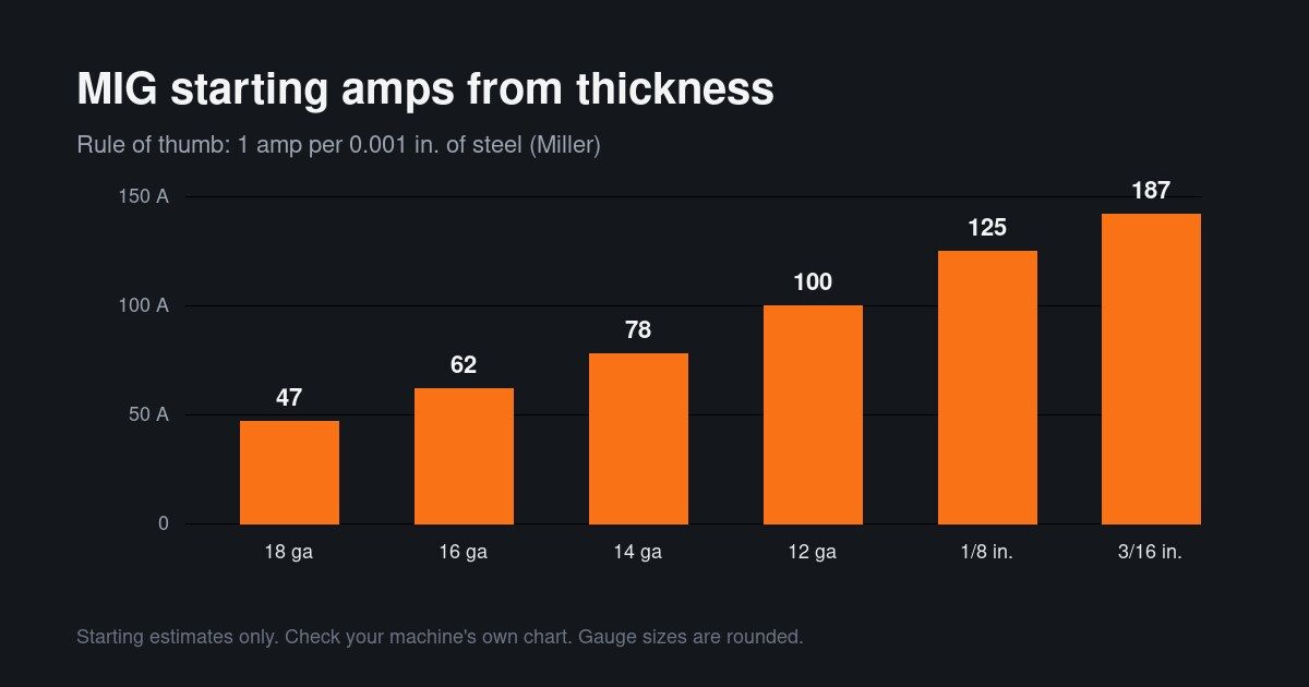
A welding amperage chart gives starting amps for a process, material thickness and electrode size. For MIG on steel, Miller's rule of thumb is 1 amp per 0.001 inch of thickness, so 1/8 inch (0.125) starts near 125 A. Stick and TIG ranges depend on rod or tungsten size, so use the charts below and your machine's own chart.
From the guide: Welding Supplies and Consumables: Wire, Rods, Shielding Gas, and Wear Parts
A welding amperage chart gives starting current for a process, a metal thickness and a rod or wire size. Use it to set a first pass, then fine-tune on scrap. This page collects published starting values from Miller and Lincoln Electric for MIG, stick and TIG, and links to the welding amperage and settings calculator that applies them to your job.
For wire, rod and gas choices behind these numbers, see our welding supplies and consumables guide. Values marked with a dagger (†) are unconfirmed: check the official table on your machine, rod box or data sheet.
Rule of Thumb: Amps by Metal Thickness
For MIG on steel, Miller’s rule of thumb is 1 amp per 0.001 inch of thickness. A 0.125 inch (1/8 in.) plate therefore starts near 125 A. Miller treats this as a starting point, with the final setting tuned for joint, position and wire.
| Steel thickness | Decimal (in.) | Starting amps |
|---|---|---|
| 18 gauge | 0.047 † | about 47 A |
| 16 gauge | 0.062 † | about 62 A |
| 14 gauge | 0.078 † | about 78 A |
| 12 gauge | 0.100 † | about 100 A |
| 1/8 in. | 0.125 | about 125 A |
| 3/16 in. | 0.187 | about 187 A |
MIG Settings: Wire Size, Amps and Wire Speed
Pick wire by amperage, then set wire speed from the burn-off rate. Miller lists burn-off in inches per amp per minute, so wire speed is amps multiplied by that rate.
| Wire diameter | Burn-off rate | Wire speed at 125 A |
|---|---|---|
| 0.023 in. | 3.5 | 437 in./min |
| 0.030 in. | 2 | 250 in./min |
| 0.035 in. | 1.6 | 200 in./min |
| 0.045 in. | 1 | 125 in./min |
Lincoln’s data sheet for SuperArc L-56 solid wire lists about 80 to 175 A for 0.035 in. and 145 to 200 A for 0.045 in. in short-circuit transfer with CO2 (†). With 75/25 argon and CO2 Lincoln says to reduce voltage by 1 to 2 V. For setup and gun technique, read our MIG welding wire guide and MIG welding for beginners.
Stick Amperage by Rod Size
Stick amperage depends on the rod type and diameter, and on AC or DC. The ranges below are from Lincoln Electric product pages (†). “DC+” means electrode positive.
| Rod | 3/32 in. | 1/8 in. | 5/32 in. |
|---|---|---|---|
| E6010 (DC+) | 50-85 A | 75-135 A | 100-175 A |
| E6011 (AC) | 40-90 A | 65-120 A | 115-150 A |
| E6011 (DC+) | 40-80 A | 60-110 A | 105-135 A |
| E6013 (AC) | 75-115 A | 110-140 A | not listed |
| E7018 (DC+) | 70-110 A | 90-160 A | 130-210 A |
| E7018 (AC) | 80-120 A | 100-160 A | 140-210 A |
Choose the rod first with our welding rods and electrodes guide and learn technique in the stick welding guide.
TIG Amperage by Tungsten Size
Miller’s TIG manual ties amperage to tungsten diameter (†):
| Tungsten | DC electrode negative | AC with high frequency |
|---|---|---|
| 1/16 in. | 50-160 A | 50-150 A |
| 3/32 in. | 135-235 A | 135-235 A |
| 1/8 in. | 250-400 A | 225-360 A |
See the TIG welding guide for torch setup, and our MIG vs TIG comparison if you are choosing between them.
Shielding Gas Flow
Published flow ranges differ by maker, so treat them as a window (†):
- MIG, Lincoln: 15 to 20 CFH, and 20 to 25 CFH out of position or in a draft.
- MIG on steel, Miller: 25 CFH for solid ER70S-6 with 75% argon and 25% CO2.
- Gas-shielded flux-core: 40 to 50 CFH with 75 to 82% argon.
- TIG argon: 15 to 35 CFH in one Miller manual.
Our shielding gas guide explains blends and drafts.
Calculator: Turn the Chart Into Your Settings
Pick your process, metal and thickness in the welding amperage calculator to get starting amps, wire or rod size and gas flow in one place. Unconfirmed values keep their label in the results.
Check Your Machine’s Own Chart
Your welder’s door chart or manual overrides any general table. A machine may not reach the current a thick plate needs, especially on 120 V power, so check its rated output and duty cycle first. See our comparison of 120V and 240V input for what each can do.
Set amps for the arc and joint you have, not the highest number you can reach. Wear the right filter lens and PPE per OSHA 29 CFR 1910.252 and our welding safety and PPE guide.
Next Steps
Estimate how long you can run at these amps with the duty cycle calculator, or compare machines in the welding machines buyer’s guide.
Disclaimer: Starting values are educational. Follow your machine manual, the consumable maker’s data sheet and applicable safety standards.
| Rod | 3/32 in. | 1/8 in. | 5/32 in. |
|---|---|---|---|
| E6010 (DC+) | 50-85 A | 75-135 A | 100-175 A |
| E6011 (AC) | 40-90 A | 65-120 A | 115-150 A |
| E6013 (AC) | 75-115 A | 110-140 A | not in data |
| E7018 (DC+) | 70-110 A | 90-160 A | 130-210 A |
Start in the middle of the printed range, move down for thin metal or vertical-up work, and move up for thicker plate. All ranges here are marked unconfirmed: check the official table on your rod's box.
Questions we get
How many amps do I need to weld 1/8 inch steel?
For MIG, Miller's rule of thumb gives about 125 amps for 1/8 inch (0.125 in.) steel. For stick, a 1/8 in. E7018 rod is printed at 90 to 160 A on DC in Lincoln's data, and a 1/8 in. E6011 at 65 to 120 A on AC. These are starting points; your machine's chart and the rod box take priority.
What wire speed should I use for MIG?
Multiply your amps by the wire's burn-off rate. Miller lists 1.6 inches per amp per minute for 0.035 wire, so 125 A needs about 200 inches per minute, and 1 inch for 0.045 wire gives about 125 inches per minute. Use this to set the feeder, then adjust voltage and wire speed by sound and bead shape.
How many amps per rod size for stick welding?
Amps rise with rod diameter and depend on the rod type. Lincoln's printed ranges for E7018 on DC are 70 to 110 A for 3/32 in., 90 to 160 A for 1/8 in. and 130 to 210 A for 5/32 in. Always use the range on the rod maker's box or data sheet, and weld toward the low end for out-of-position work.
What gas flow rate should I set?
For MIG, Lincoln lists 15 to 20 CFH, with 20 to 25 CFH out of position or in drafts, while Miller lists 25 CFH for solid wire with 75% argon and 25% CO2. A Miller TIG manual prints 15 to 35 CFH of argon. Flow ranges differ by manufacturer, so use your machine's manual.
Do welding settings change on a 110V machine?
The chart does not change but the machine may not reach it. A 120 V welder can have a lower maximum output than the 125 amps that 1/8 inch steel suggests, so you may need multiple passes or a 240 V machine. See our 110V vs 220V guide and your machine's rated output and duty cycle before choosing.
Where we got this
- Miller Electric: MIG Welding, Setting the Correct Parameters (millerwelds.com)
- Miller Electric: MIG welding instructor guide (rule of thumb and wire burn-off) (millerwelds.com)
- Miller Electric: TIG owner's manual OM-2233, tungsten electrode amperage ranges (millerwelds.com)
- Lincoln Electric: Fleetweld 5P+ (E6010) product page, typical operating procedures (prodcd.lincolnelectric.com)
- Lincoln Electric: Fleetweld 180 (E6011) product page, typical operating procedures (prodcd.lincolnelectric.com)
- Lincoln Electric: Fleetweld 37 (E6013) product page, typical operating procedures (prodcd.lincolnelectric.com)
- Lincoln Electric: Excalibur 7018 MR (E7018-1) product page, typical operating procedures (lincolnelectric.com)
- Lincoln Electric: SuperArc L-56 (ER70S-6) data sheet C110 (lincolnelectric.com)
- OSHA 29 CFR 1910.252: Welding, Cutting, and Brazing, General Requirements (osha.gov)
Keep reading
- Welding Supplies and Consumables: Wire, Rods, Shielding Gas, and Wear Parts
Complete guide to welding supplies and consumables: MIG wire (ER70S-6), stick electrodes (E7018, E6011), shielding gases, TIG tungsten, and gun parts.
- MIG Welding Wire Guide: Types, Sizes and Choosing the Right Wire
Learn how to choose MIG welding wire by AWS class (ER70S-6, ER70S-2, aluminum, stainless) and wire diameter (.023, .030, .035, .045) for your steel.
- Shielding Gas for MIG and TIG: Argon, CO2 and Mixes
Compare C25 (75/25 argon-CO2), 100% CO2, and pure argon shielding gases for MIG and TIG welding, plus CFH flow rates and gas cylinder safety rules.
- Welding Rods and Electrodes Guide: 6010, 6011, 6013, 7018 Explained
Understand AWS stick electrode numbers and compare 6010, 6011, 6013, and 7018 welding rods by polarity, amperage range, penetration, and storage.